We are factory and we have many certified suppliers of the
compressor parts, so we can offer all kinds of screw & scroll
compressor parts with high quality and competitive price.
*100
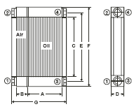
|
Specification Oil cooler / air aftercooler |
|
Order number |
114277 |
115214 |
|
Technical data (standard values) |
|
Compressor
driving power |
kW/HP |
18.5 / 25 |
22 / 30 |
30 / 40 |
|
Oil cooler
output |
kW/HP |
15.7 / 21.2 |
18.7 / 25.4 |
25.5 / 34 |
|
Air aftercooler
output |
kW/HP |
2.7 / 3.7 |
3.3 / 4.4 |
4.3 / 5.8 |
|
Oil circulation
volume |
l/min |
33 |
40 |
45 |
|
Compressed air
volume |
Nm³/min |
2.9 |
3.6 |
4.8 |
|
|
cfm |
71 |
106 |
141 |
|
Oil inlet
temperature |
°C/°F |
max. 110 / 230
|
|
Compressed air
inlet temperature |
°C/°F |
|
Total cooling
air volume |
kg/h |
3300 |
3960 |
5460 |
|
Backpressure at
front of cooler |
mmWG |
ca. 20 |
|
Cooling air
temperature |
°C/°F |
max. 45 / 113 |
|
Approximate
cooler dimensions |
|
A |
mm/inch |
320 / 12.60“
|
320 / 12.60” |
|
B |
mm/inch |
108 / 4.25”
|
108 / 4.25” |
|
C |
mm/inch |
548 / 21.58“
|
530 / 20.87” |
|
D |
mm/inch |
65 / 2.56“
|
97 / 3.82”
|
|
E |
mm/inch |
621 / 24.45“
|
620 / 24.41”
|
|
F |
mm/inch |
686 / 27.01“
|
684 / 26.93”
|
|
G |
mm/inch |
481 / 18.94“
|
487 / 19.17”
|
|
max. working
pressure |
bar (g)/psig
|
15 / 218 |
|
Connection 1 -2
(air) |
inch |
G ¾” |
|
Connection 3 -4
(oil) |
inch |
G ½” |
|
Cooler weight
approx. |
kg/lb |
487 / 19.17”
|
487 / 19.17”
|
|
Fan speed |
min-1 |
~ 2500 |
|
Fan diameter |
mm/inch |
~ 450 / 15.75”
|
*160
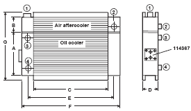
|
Specification Oil cooler / air aftercooler |
|
Order number |
114367 |
114368/100900 |
|
Technical data (standard values) |
|
Compressor
driving power |
kW/HP |
37 / 50
|
45 / 60 |
55 / 75 |
|
Oil cooler
output |
kW/HP |
31 / 41
|
38 / 51 |
47 / 64 |
|
Air aftercooler
output |
kW/HP |
6 / 8
|
7 / 9 |
8 / 11
|
|
Oil circulation
volume |
l/min |
43 |
45 |
60
|
|
Compressed air
volume |
Nm³/min |
5.6 |
6.3 |
7.1 |
|
|
cfm |
177 |
212 |
247 |
|
Oil inlet
temperature |
°C/°F |
max. 110 / 230
|
|
Compressed air
inlet temperature |
°C/°F |
|
Total cooling
air volume |
kg/h |
6720 |
8100 |
9900 |
|
Backpressure at
front of cooler |
mmWG |
ca. 25 |
|
Cooling air
temperature |
°C/°F |
max. 45 / 113 |
|
Approximate
cooler dimensions |
|
A |
mm/inch |
490
/ 19.29“ |
553 / 21.77“ |
|
B |
mm/inch |
135
/ 5.31“ |
188 / 7.40“ |
|
C |
mm/inch |
548
/ 21.57“ |
690 / 27.17“ |
|
D |
mm/inch |
65 / 2.56” |
113 / 4.45“ |
|
E |
mm/inch |
-- -- |
-- |
|
F |
mm/inch |
670 / 26.38“ |
840 / 33.07“ |
|
G |
mm/inch |
685
/ 26.97“ |
801 / 31.54“ |
|
max. working
pressure |
bar (g)/psig
|
15 / 218 |
|
Connection 1 -2
(air) |
inch |
G 1½” |
|
Connection 3 -4
(oil) |
inch |
G 1” |
|
Cooler weight
approx. |
kg/lb |
37 / 82 |
|
Fan speed |
min-1 |
~ 2200 |
|
Fan diameter |
mm/inch |
~ 470 / 15.75”
|
*250
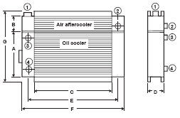
|
Specification Oil cooler / air aftercooler |
|
Order number |
114274 |
|
|
|
Technical data (standard values) |
|
Compressor
driving power |
kW/HP |
75 / 100 |
90/ 125 |
110 / 150 |
|
Oil cooler
output |
kW/HP |
64/ 87 |
76 / 106 |
93 / 128 |
|
Air aftercooler
output |
kW/HP |
11 / 15 |
14 / 19 |
17 / 22 |
|
Oil circulation
volume |
l/min |
80 |
90 |
110 |
|
Compressed air
volume |
Nm³/min |
10 |
14 |
17 |
|
|
cfm |
353 |
495 |
600 |
|
Oil inlet
temperature |
°C/°F |
max. 110 / 230
|
|
Compressed air
inlet temperature |
°C/°F |
|
Total cooling
air volume |
kg/h |
13200 |
16200 |
19500 |
|
Backpressure at
front of cooler |
mmWG |
ca. 25 |
|
Cooling air
temperature |
°C/°F |
max. 45 / 113 |
|
Approximate cooler dimensions |
|
A |
mm/inch |
534
/ 21.02“ |
776 / 30.55“ |
|
B |
mm/inch |
261
/ 10.28“ |
303 / 11.93“ |
|
C |
mm/inch |
850
/ 33.46“ |
1000 / 39.37“ |
|
D |
mm/inch |
113
/ 4.45“ |
113 / 4.45“ |
|
E |
mm/inch |
920
/ 36.22“ |
1070 / 42.13“ |
|
F |
mm/inch |
1035
/ 40.75“ |
1150 / 45.28“ |
|
G |
mm/inch |
870
/ 34.25“ |
1075 / 42.32“ |
|
max. working
pressure |
bar (g)/psig
|
15 / 218 |
|
Connection 1 -2
(air) |
inch |
G2” |
|
Connection 3 -4
(oil) |
inch |
G 1¼” |
|
Cooler weight
approx. |
kg/lb |
8.5 / 18 |
98 / 216 |
|
Fan speed |
min-1 |
~ 1450 |
|
Fan diameter |
mm/inch |
~ 550 / 21.65” |
630 / 24.80” |
700 / 27.56” |
Cooling Fan
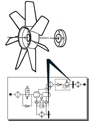
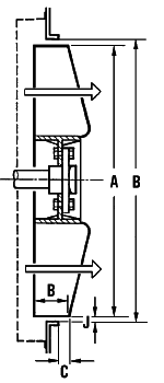
In the case of
air-cooled screw compressor systems, the cooling air is pressed through
the cooler fins by the fan. Axial-designed fans are used for this more
often than radial-designed fans. The fan impellers, which are mounted on
the driving shaft by means of a suitable hub, are an important component
of the system. Depending on the cooler design, the fans can be used to
draw air in or push air out. Each fan only achieves optimum operational
performance at
specific speed and application ranges. The selected cooling concept is
one of the essential factors when designing the screw compressor system.
The maximum permissible operational temperatures, in most cases 100°C /
212°F at ambient temperatures of up to 40°C / 104°F, must not be
exceeded. The flow of heated cooling air through air ducts results in an
increased resistance which must be overcome by the fans. The selected
air duct cross-section should not be smaller than the entire cooler
surface. If a long air duct with several bends is used an additional fan
must be installed. The less clearance J there is between the fan blade
edge and the inner diameter of the guide ring J = O - A/2, the better
the air output will be. Variations of penetration depth C affect the air
output quality (see diagram). All of the characteristic curves specified
by us assume a clearance of J = 1% A and a penetration depth of C -B/3
|
Order Number |
Nominal size |
Number of blade |
Rotation direction |
Speed* |
.Power Range |
|
ø mm |
|
Right/Left |
min-1 |
kW |
|
113927 |
276 |
6 |
Right |
2950 |
7.5 |
|
112554 |
Left |
|
107744 |
320 |
2600 |
11 |
|
105890 |
340 |
7 |
Right |
|
107618 |
350 |
6 |
Left |
15 |
|
103894 |
380 |
7 |
Right |
2400 |
22 |
|
108695 |
430 |
30 |
|
103440 |
450 |
2200 |
45 |
|
103752 |
6 |
Left |
|
112565 |
470 |
7 |
Right |
55 |
|
112432 |
630 |
9 |
Left |
1700 |
110 |
|
112418 |
700 |
1400 |
Note: If you are
interested in our designs and details, please contact us for a quote
text &products presentation.
